If you’ve read my article on Macagotchi for the Pi, you’ll know that I like to use the Pi Zeros for my projects. That project used a Zero 2W, but recently I was able to grab a second hand Pi Zero WH for ~8 USD. I’ll be using it for a big project later on (stay tuned!), but while I wait for the other components to arrive, I started playing around with it. The Pi didn’t come with a heatsink, so would get warm over time. If it got too warm, I could easily cool it down by blasting it with a hand fan. To help me with this, I wrote a script that uses the Pi’s GPIO pins to control an LED’s brightness based on the CPU’s temperature.
If you’ve already got your Pi set up, click here to skip to the code.
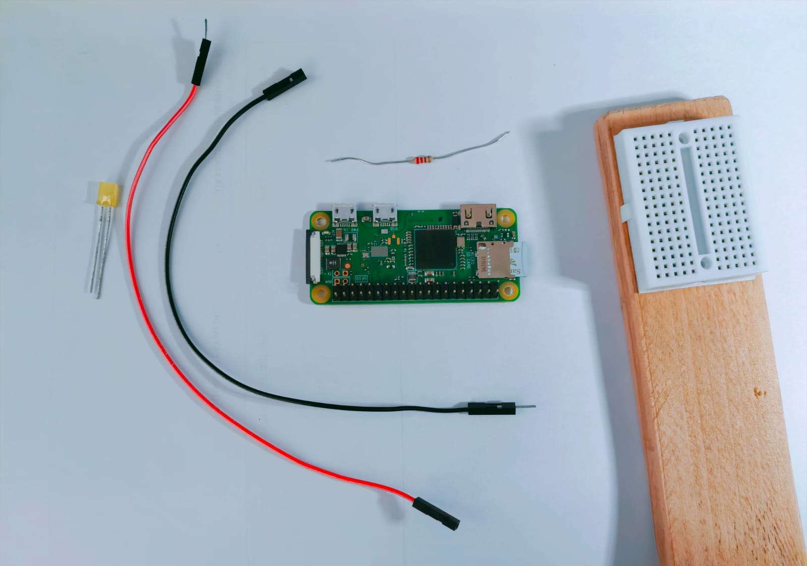
Required components
- A Pi Zero / Zero 2 with headers (H). I suggest getting one with wireless support (W) for ssh. You can use other Pi models, just make sure to double check the pinout.
- Two female to male jumper wires
- 220 Ω resistor
- An LED
- Breadboard
- Micro USB cable to power the Pi
- Micro SD card for the OS
- Micro HDMI cable (optional)
Flashing the OS
For the Pi to work, it needs a micro SD card with Raspbian flashed to it. The easiest way to do this is to use the official Raspberry Pi imager, which will flash the OS for you and help you configure the Pi ahead of time.
Select the Pi model you’re using (Pi Zero / Pi Zero 2 W).
For the operating system, select Raspberry Pi OS (other) > Raspberry Pi OS Lite (32-bit) for the Pi Zero, and Raspberry Pi OS (other) > Raspberry Pi OS Lite (64-bit) if you’re using the Pi Zero 2. For “storage” select your microSD card. Make sure that you don’t select any other drive, as the contents will be wiped.
When you press Next, you’ll be given an option to modify the settings of the pi. Here you can set up WiFi, ssh, the hostname and your log in. Make sure to enable SSH.
Make sure that the WiFi network you’re using is 2.4ghz and not 5ghz, as Pi’s don’t support 5ghz
If you had trouble getting the official imager to work, you can flash the OS Image using another image flashing software, such as Balena etcher or dd. You’ll just have to connect a keyboard and monitor and set up WiFi, hostname, login and SSH manually, via
sudo rpi-config
Connecting to the Pi Zero
To connect to the Pi, we’ll be using ssh. Plug a micro-USB cable into the port marked PWR-IN (not USB). The other end of the cable should be plugged into a USB wall plug. You may have to experiment with different power sources, as Pi’s can be quite picky about power draw. Once you see a flashing green light next to the PWR-IN port, you’ll know that you’ve found a suitable power source. Give it a few minutes to boot up and connect to WiFi.
Then, in a unix command line or powershell, run the command
ssh [username]@[hostname].localThe first time you connect to the Pi, you might see a message like:
The authenticity of host '[hostname].local (192.168.1.1)' can't be established.
ED25519 key fingerprint is SHA256: ..............
This key is not known by any other names.
Are you sure you want to continue connecting (yes/no/[fingerprint])?
Type yes and press enter.
What does this message mean?
Whenever you ssh to a device, it has a specific “fingerprint” that your computer uses to check if the device is the same device that you’ve connected to before. This is to prevent other devices pretending to be your Pi, so that you give them the Pi’s log in details, or so that they can run malicious stuff on your computer. When you say “yes” you’re adding this fingerprint to your computer’s list of “trusted” fingerprints.
After this, you’ll be asked for the password for your user. Type it in and press enter.
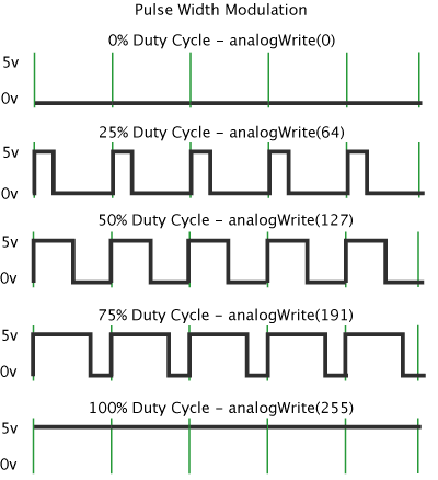
Power Width Modulation
Before we get into the code, I have to explain how we can control the brightness of the LED. Most microcontrollers and all Pi’s cannot change the output voltage of their GPIO pins. Instead, they user PWM or Power Width Modulation. Essentially, they switch the pin’s power on and off very quickly, based on a “duty cycle”. The “duty cycle” represents how often the pin’s power should be on. Because the pin’s power is being toggled so quickly, it tricks our brains into seeing a brighter or dimmer led. A higher duty cycle means a brighter LED, a lower duty cycle means a dimmer one.
Here’s a diagram of what “Power Modulation” looks like. This graph is based on how arduino’s use PWM, where the duty cycle is between 0 and 255, instead of 0 and 100, and the output voltage is 5 volts instead of 3.3, but the basic concept is the same.
The code
Now that you’re connected to the pi, we can finally start installing the packages we need, and write our python script.
We only need to install two packages for this project, python3 (to run our code) and nano (to write the code to a file).
sudo apt get install python3
sudo apt get install nano
Now, to create our main.py script, run
nano main.pyHere’s the code. I’ll explain each bit as we go along.
import RPi.GPIO as GPIO
import time
import subprocess
RPi.GPIO lets us control the Pi’s GPIO pins, and subprocess allows us to run command line commands from python.
LED_PIN = 17
PWM_FREQ = 1000

MIN_TEMP = 40.0
MAX_TEMP = 60.0
LED_PIN is the pin that we will connect to the positive terminal of our LED and control via PWM. Not all pins on the Pi support PWM. If you’re using a different model of Pi (not a Pi Zero / Zero 2W), you may need to change this variable. PWM_FREQ sets out PWM frequency at 1000hz . MIN and MAX_TEMP define the temperature range we’ll use: 40°C to 60°C. This means the LED will be off for any temps below 40°C, and max brightness at 60°C. Feel free to adjust this range to better suit you.
GPIO.setmode(GPIO.BCM)
GPIO.setup(LED_PIN, GPIO.OUT)

pwm = GPIO.PWM(LED_PIN, PWM_FREQ)
pwm.start(0)
setmode() tells the Pi that we’ll be using the Broadcom pin number standard for stating which pin we want to use (more on this in a bit). GPIO.setup() tells the Pi that we’ll be using pin 17 for output. The pwm variable allows us to output from pin 17 using PWM.
def get_cpu_temp():
    result = subprocess.run(
        ["vcgencmd", "measure_temp"],
        capture_ouput=True,
        text=True
    )
    temp_str = result.stdout.strip().split("=")[1].replace("'C","")
    return float(temp_str)
This function uses subprocess to run vcgencmd measure_temp, and extracts the temperature as a float.
try:
    while True:
        rawtemp = get_cpu_temp()
        temp = rawtemp
        if temp < MIN_TEMP:
            temp = MIN_TEMP
        elif temp > MAX_TEMP:
            temp = MAX_TEMP

        duty_cycle = ((temp - MIN_TEMP) / (MAX_TEMP - MIN_TEMP)) * 100.0

        pwm.ChangeDutyCycle(duty_cycle)

        print(f"CPU: {rawtemp:.1f} °C → PWM: {duty_cycle:.1f}%")

        time.sleep(1)
This code gets the CPU temp, clamps it to our temperature range, and maps that to a range between 0 and 100. Pin 17 then uses that number as a PWM output. Then the code sleeps for 1 second and loops.
except KeyboardInterrupt:
    pass

finally:
    pwm.stop()
    GPIO.cleanup()
This code tells pin 17 to stop outputting PWM when a keyboard interrupt (Ctrl+c) is detected.
When you keyboard interrupt, you might get an error like this:
Traceback (most recent call last):
  File "/usr/lib/python3/dist-packages/RPi/GPIO/__init__.py", line 179, in __del__
  File "/usr/lib/python3/dist-packages/RPi/GPIO/__init__.py", line 202, in stop
  File "/usr/lib/python3/dist-packages/lgpio.py", line 1084, in tx_pwm
TypeError: unsupported operand type(s) for &: 'NoneType' and 'int'
This is a known issue with the RPi.GPIO library. It shouldn’t affect your Pi (at least for this project).
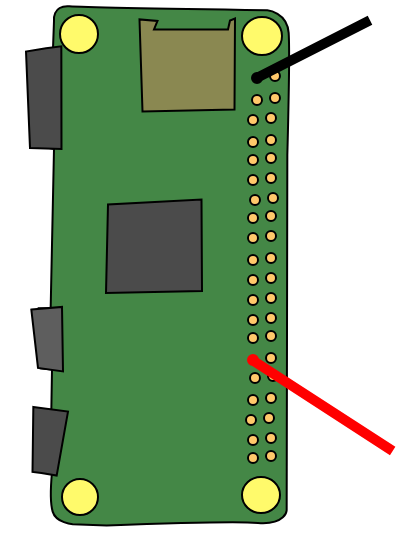
Wiring the GPIO up
Time to connect our pins to the LED! The “Pin 17” in our code doesn’t actually refer to the Pi’s 17th pin. This is because we’re using the BCM standard to number our pins. There are plenty of diagrams online which show you the numbers of the pins on the Pi Zero and Zero 2 and where to find them. The image below shows you where to connect your positive (red) jumper wire and negative (black) jumper wire. If you’re using a different model of Pi, make sure to double check its pinout.
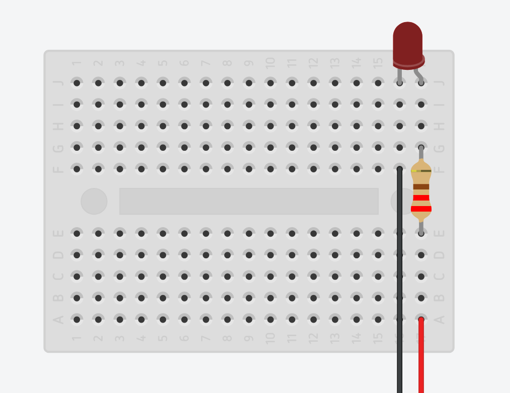
Wire up the breadboard like this
Now, in your ssh session, simply run:
python3 main.pyResults
I left main.py running while I installed some packages. Here’s a time-lapse of the LED.

I hope that you found this mini Pi Zero project interesting. If you did, why not checkout my other project on a Pi Zero 2W, Macagotchi for the pi?