
In my last two blog posts, I gave my robot a face, the ability to track faces, and a little servo to move in real time based on the position of my face. To let that servo actually control and move the face of the robot, I needed to design and 3D print a custom mount, which the servo would connect to and the phone would sit on.
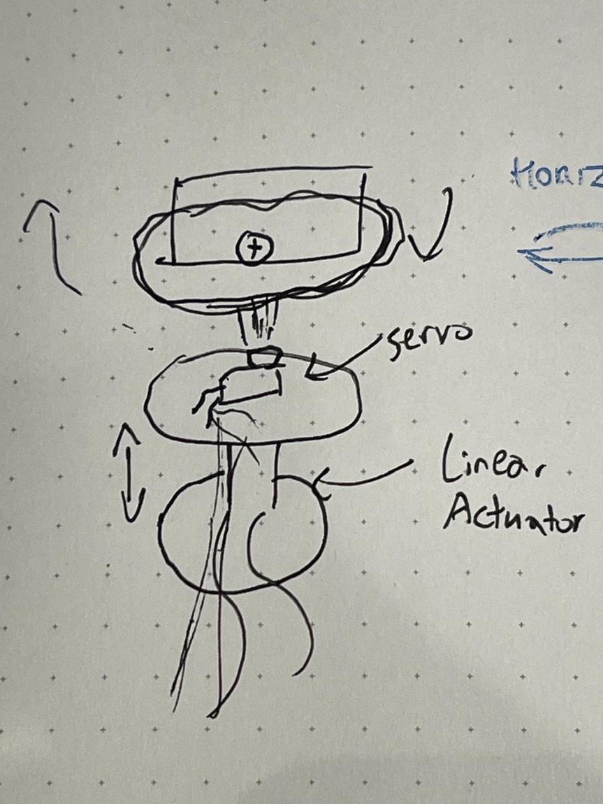
I don’t expect it to make much sense as it’s pretty messy, but this is a sketch of what I had in mind, before actually designing the part in CAD.
Designing the Part
This started by creating a digital replica of the “horns” that came with my servo. I placed the horn on my printer’s scanner, along with a ruler to set the scale. Then I traced it in Fusion 360, measuring the horn with a ruler to make adjustments. Afterwards, I had a 2D copy of the horn, with some measurements for the extruded sections.
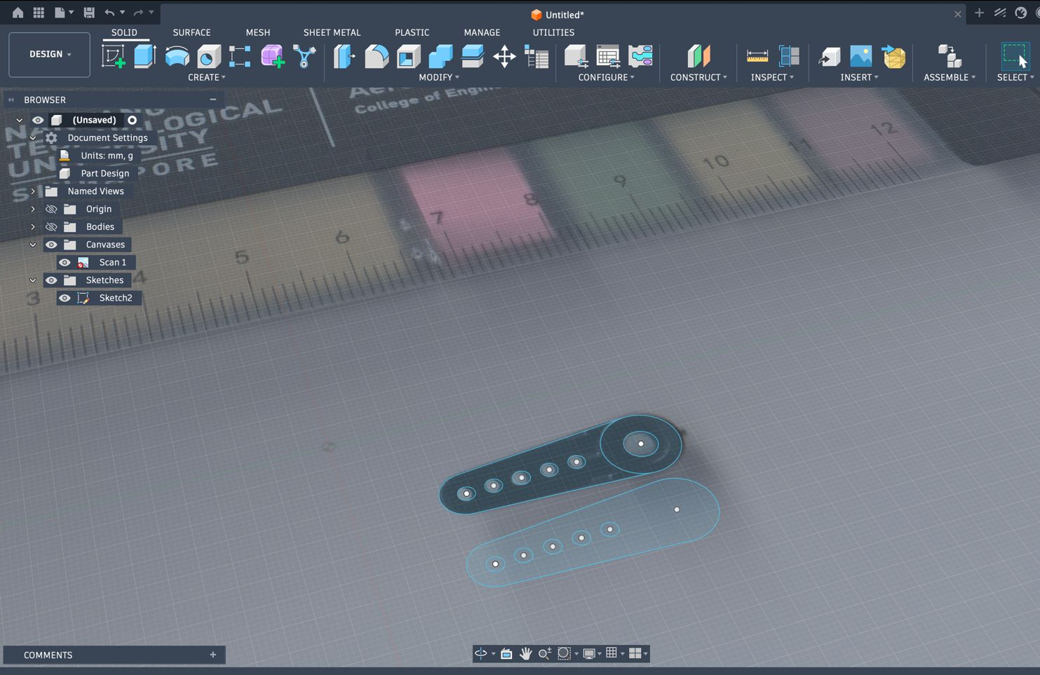
Using that, I modeled the main “turntable” section of the part, and cut a recess into it, where the horn would sit. I made a long but narrow guiding hole, aligned with one of the screw holes on the horn, which a screw would screw into. I also added a small bump, to support the non extruded part of the horn
Getting it 3D Printed
Since I don’t have a 3D printer at home, I ordered the turntable to be printed out of nylon from JLC3DP (not sponsored). After the file review process, I got an email from them warning that the length of the part could lead to printing issues, asking if I was willing to take the risk. I decided to take the risk. As I waited for the parts to arrive, I worked on the robot’s expressions (stay tuned for an article on that). It arrived with no manufacturing defects as far as I could tell.
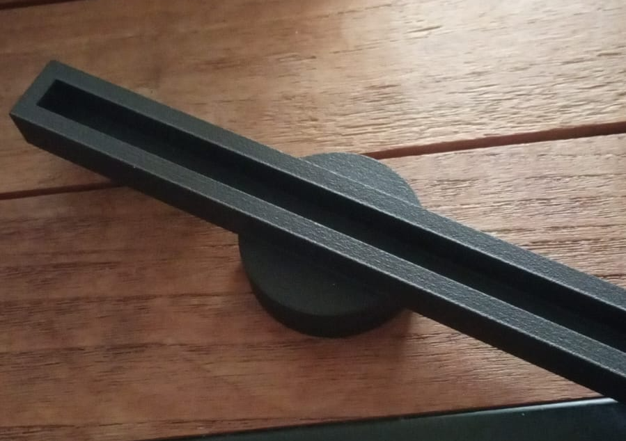
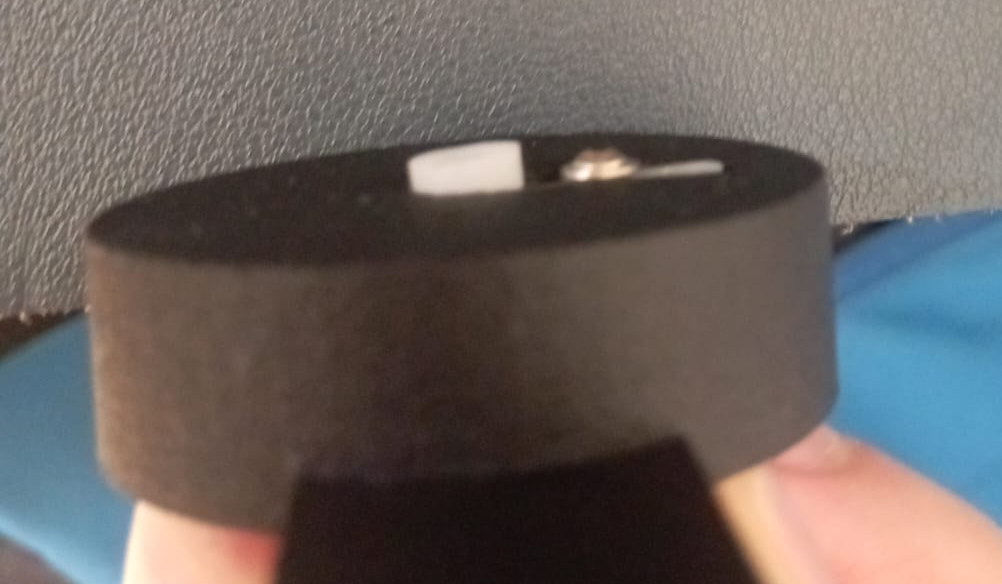
When I tried to connect the turntable to one of the servo horns, I realised that I had made the cut out slightly too narrow, and too long. I filed down the sides of the horn until it could fit tightly, before I screwed it in.
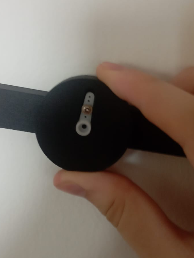
Then I realised I had designed the slot in the turntable for a different horn. That meant that the square bump I had extruded from the slot to help support the thinner part of the horn was too thick, and made the horn angle up, away from the center of the turntable. Screwing directly into the nylon meant the screw was stuck in place.
The Demo
Having no way to remove the horn, I decided to test the part on the servo anyway. After moving, the servo would try to “fight” against the chaotic movement and weight shift caused by the instability. Often, it would overcorrect, leading to the servo constantly making shifts back and forth.
The red eyes are a debug feature for when the model loses track of the face
This was one idea for the robot design that I had in mind. As I was waiting for the 3D part to arrive, I’d already begun exploring a different design. Given the issues I’ve had with this design, I’ve decided to go with that plan.
Stay tuned for an update on how that goes!